Most people usually encounter MotionBuilder for the first-time when they want to animate a character with motion capture. And the first question they usually have is, “how do I rig a character for editing motion capture in MotionBuilder?”
This was certainly the case when I first started using it back in 2000 at Acclaim Entertainment. To make our PlayStation 2 game more “next-gen” it was decided all the character animation would be motion captured and then edited in MotionBuilder, or Kaydara FilmBox as it was called back then. The only problem was, I knew how to rig a character for animating in Max and Maya, but not for editing motion capture in MotionBuilder. Suddenly I found myself with a long list of questions:
- How do I rig a character for MotionBuilder?
- Do I rig it in Maya or in MotionBuilder?
- What joints do I need to build?
- Does the rig need IK?
- Do I need to use the MotionBuilder naming convention?
- What rig do I send to a Motion Capture Company?
Well, it turns out rigging a character for MotionBuilder is pretty much the same as rigging a character for any software:
- Start with a good character mesh.
- Add accurately placed joints with clean translation and rotations values.
- Name them correctly.
- Set the joint orientation and rotation orders.
- Skin them to the mesh.
The only difference is, you only need to build the joints. All you need to animate a character in MotionBuilder is a continuous Forward Kinematic (FK) skeleton hierarchy skinned to a mesh. No IK handles. No animation controls. No broken hierarchies. All this will be taken care of by the Full Body FK/IK Control Rig in MotionBuilder.
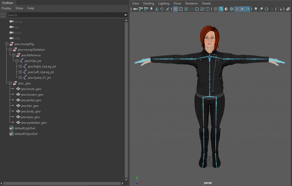
So, that’s exactly what I’m going to show you in this tutorial. Everything you need to know to rig your character for MotionBuilder: what joints to create, where to place them, how to build them, what to call them, and which software to do it in.
When you’ve finished you’ll have a rig you can export to MotionBuilder ready to Characterize, apply some mocap and start editing.
Before you Begin
While it’s tempting to rush in and start creating joints, there are a few things you should do before you begin to avoid problems later.
Check the Mesh
The mesh will determine exactly where you’ll put the joints so you must make sure you have the correct version before you start. Any problems at this stage could mean headaches and reworks later.
- Check Geometry: MotionBuilder only supports Polygons and Nerbs geometry. If you’ve used something else, for example sub-divisional surfaces, you’ll need to convert them before exporting to MotionBuilder.
- Check Version: Always check you have the correct version of the character mesh before you start rigging your character. There’s nothing worse than building a rig, only to find you need to reposition all the joints because you’ve been working with the wrong mesh. This becomes even worse if you’ve already captured and edited some motion for it.
- Freeze Transforms: Freeze the transformations of the geometry to remove the translation, and rotation values and set the scale to 1. While these values work correctly in your current 3d package, they may not produce the same results in MotionBuilder.
- Delete History: Remove all the construction history from the geometry. Only skin modifiers and blend shapes can be exported to MotionBuilder. Everything else will be lost as it’s very rare for this kind of information to transfer correctly between 3D packages.
- Character Scale: Ideally your character should be real-world size, for example 1.8m or 5’8” tall. This will make it much more compatible with MotionBuilder and the data from Motion Capture systems. Also, very small or very large characters can cause calculation errors for some solvers, for example, IK and Human IK. If you do have to work at a different scale, you can parent the hip joint of your character to a “Reference” node so it can be rescaled in MotionBuilder.
- Character Alignment: Ideally the character should be standing upright at the centre of the scene, with both feet on the floor, facing down the +Z axis (looking at you in a front view).
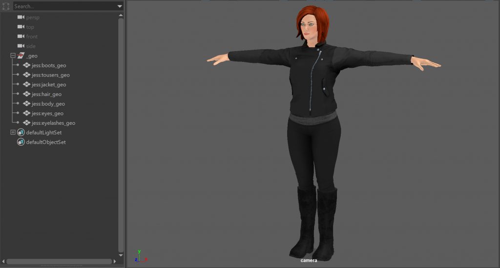
- Correct Naming: Check every piece of geometry is named correctly. You should be able to tell exactly what something is from its name. Adding “_mesh” or “_geo” to the end of the name will also help identify what type of object it is. Handy if you need to select all the geometry in your scene by name.
Creating a Joint Naming Convention
First thing to say is, YOU DO NOT NEED TO USE THE MOTIONBUILDER NAMING CONVENTION. This only helps automate the Mapping Process. If you use your own joint names you can manually complete the mapping process and create a Naming Template to automate the process next time.
As every project and facility usually has its own naming convention, the following is meant as a guide to help you create your own. The most important thing to remember is keep the names simple, descriptive, and consistent.
- Simple: Make the joint names as simple as possible. While medical names like Humerus > Ulna > Carpus are anatomically correct, UpperArm > LowerArm > Hand is much easier for everyone to understand. Also, try to avoid long names or names with lots of abbreviations as these can be difficult to read. For example, “LeftHandSide_ShoulderArmJoint_ForMocapSkeleton” or “Lft_UprLg_Mcp_Jnt”
- Descriptive: The name should describe which limb the joint represents and where it is in the hierarchy. For example, start the name with “Left_” and “Right_” for joints on different sides of the character. Add numbers to joints in a chain like the spine, neck, and finger joints. Use “_joint” or “_mocapJoint” to identify what type of object the joint is. This additional information is also useful for selecting groups of joints by name or to script certain actions.
- Consistent: Avoid mixing the types of words used in the joint names. For example, Humerus > LowerArm > handBone. Giving them similar names like UpperArm > LowerArm > Hand or Shoulder > Elbow > Wrist will make it easier for people to guess what other joints might be called. Also, use the same joint names for all your character rigs. This lets you create a character template to automate the mapping process in MotionBuilder and create scripts to automate certain processes.
- Namespaces: If all your characters have the same joints names, you will need to add them to a Namespace. This will stop them being automatically renamed by the software to avoid naming conflict (2 objects in a scene cannot have the same name unless they are in different hierarchies).
- Lock Names: Finalise the joint names before you do any mocap. Once you’ve decided on the joint names, avoid changing them unless it is necessary. Changing the names halfway through a project can break a lot of things and make lots of people very angry.
Using the MotionBuilder Joint Naming Convention
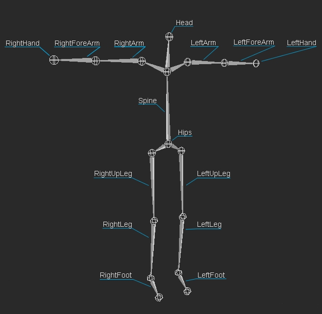
- Base (required)
- Hips
- LeftUpLeg
- LeftLeg
- LeftFoot
- RightUpLeg
- RightLeg
- RightFoot
- Spine
- LeftArm
- LeftForeArm
- LeftHand
- RightArm
- RightForeArm
- RightHand
- Head
- Auxiliary
- LeftToeBase
- RightToeBase
- LeftShoulder
- RightShoulder
- Neck
- LeftFingerBase
- RightFingerBase
- Spine
- Spine1
- Spine2
- Spine3
- Spine4
- Spine5
- Spine6
- Spine7
- Spine8
- Spine9
- Neck
- Neck1
- Neck2
- Neck3
- Neck4
- Neck5
- Neck6
- Neck7
- Neck8
- Neck9
- Left/Right Fingers
- Left/RightHandThumb1
- Left/RightHandThumb2
- Left/RightHandThumb3
- Left/RightHandThumb4
- Left/RightHandIndex1
- Left/RightHandIndex2
- Left/RightHandIndex3
- Left/RightHandIndex4
- Left/RightHandMiddle1
- Left/RightHandMiddle2
- Left/RightHandMiddle3
- Left/RightHandMiddle4
- Left/RightHandRing1
- Left/RightHandRing2
- Left/RightHandRing3
- Left/RightHandRing4
- Left/RightHandPinky1
- Left/RightHandPinky2
- Left/RightHandPinky3
- Left/RightHandPinky4
- Left/RightHandExtraFinger1
- Left/RightHandExtraFinger2
- Left/RightHandExtraFinger3
- Left/RightHandExtraFinger4
- Left/Right Toes
- Left/RightFootThumb1
- Left/RightFootThumb2
- Left/RightFootThumb3
- Left/RightFootThumb4
- Left/RightFootIndex1
- Left/RightFootIndex2
- Left/RightFootIndex3
- Left/RightFootIndex4
- Left/RightFootMiddle1
- Left/RightFootMiddle2
- Left/RightFootMiddle3
- Left/RightFootMiddle4
- Left/RightFootRing1
- Left/RightFootRing2
- Left/RightFootRing3
- Left/RightFootRing4
- Left/RightFootPinky1
- Left/RightFootPinky2
- LeftFootPinky3
- Left/RightFootPinky4
- Left/RightFootExtraFinger1
- Left/RightFootExtraFinger2
- Left/RightFootExtraFinger3
- Left/RightFootExtraFinger4
- Roll
- LeftUpLegRoll
- LeftLegRoll
- RightUpLegRoll
- RightLegRoll
- LeftArmRoll
- LeftForeArmRoll
- RightArmRoll
- RightForeArmRoll
Gather Reference
Your character needs to move like a real person, but using a much simpler skeleton (rig).
Skeletal motion is extremely complex, involving soft tissue, cartilage, and joints, all rotating around different pivots. Building a rig that accurately recreated this movement would require a rig so complex it would be unusable.
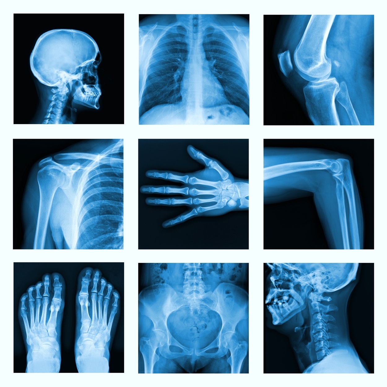
Your rig needs to find the right balance between simulating the way real joints move and usability. Too many joints and rig becomes slow and difficult to work with. Too few and you won’t be able to achieve realistic looking motion and mesh deformation.
Research everything you can about how a real body moves before you create any joints for your character:
- Look at anatomy books,
- Watch videos,
- Investigate medical sites,
- Research where joints are located and how to identify them
- Study how they move.
GATHER AS MUCH REFERENCE AS POSSIBLE. The better you understand the anatomy of your character, the easier it will be to create a rig that behaves realistically.
Building the rig
Even though you are going to be building a relatively straightforward FK skeleton, don’t be tempted to rush it. Your rig needs to recreate all the complex movement of a real skeleton, but using a lot less joints. It’s not as easy and throwing a few joints into the mesh, applying a skin modifier and sending it off for motion capture.
Your “simple” FK MotionBuilder rig is often the foundation of your entire mocap pipeline: It doesn’t contain any complex rigging which makes it an ideal way to transfer mocap to other rigs; the simple structure makes it compatible with most 3D software; it’s easy to understand and debug if something goes wrong; light enough (i.e. won’t slow scene interaction/playback) to be rigged to “drive” more complex rigs in the same scene; and the perfect rig to send to your external mocap service provider.
With so many potential uses, it’s important you make it as accurate and user-friendly as possible. If it doesn’t produce mocap data in a clean, reliable, and consistent way, you’ll spend more time fixing problems and less time doing the fun stuff.
Minimum “Base” Joints
On some projects, you might want to limit the number of joints in your rig. For example, to reduce the amount of data created or because certain joints won’t be captured or animated in MotionBuilder. To make your rig compatible with the Control Rig inside MotionBuilder, it must contain at least the following set of 15 “Base” joints.
Plan Joint Placement
Before you start rigging your character you need to have an idea where you’re going to place the joints.
Remember all that reference you gathered together earlier, go back and look at it again. Try to figure out where the major skeleton joints are in the body. Look for bony landmarks just under the surface of the skin (in blue) to use as reference points, for example:
- Clavicle and acromion process,
- 7th Cervical vertebra,
- Sacrum
- Lateral and Medial Epicondyle of Humerus,
- Styloid process of Radius and Ulna
- Greater trochanter,
- Lateral and Medial Epicondyle,
- Lateral and Medial Malleolus
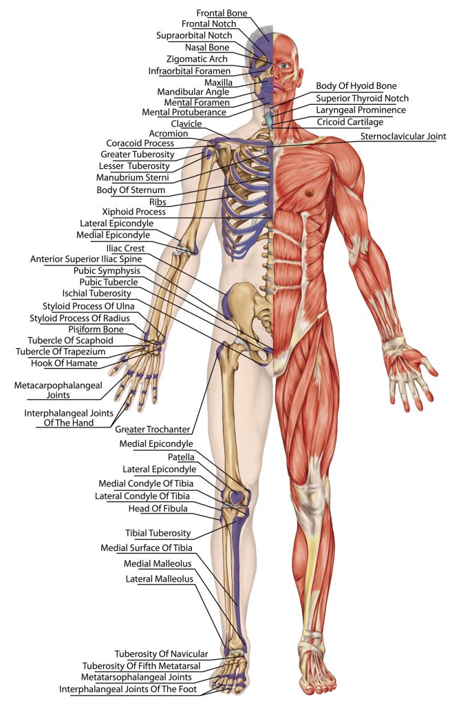
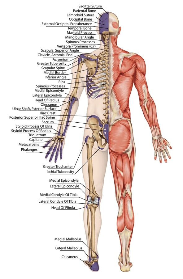
If you already have some mocap, and your performer and character are the same size (ideally, they should be), you can use the marker positions to help place the joints. This does mean you will need to know where the markers were put on the performer or have images for reference. The marker data can be imported into Maya or Max as locators. All you need to do is find a frame where your character and performer are in the same position, for example a T-Pose, and away you go.
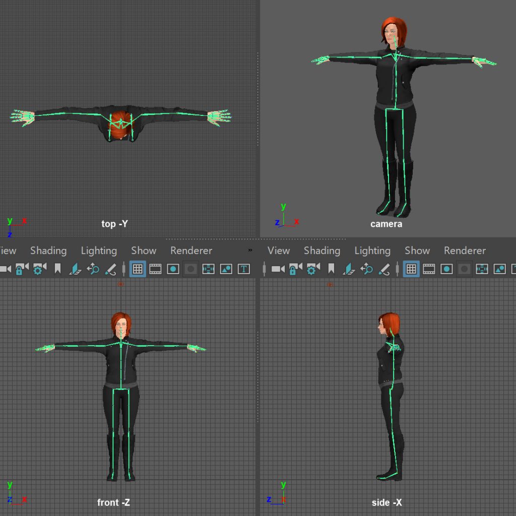
The following joint suggestions are meant as a guide to help you get started. While they work well for this character, they may not work as well for yours.
- Hips
- Single joint
- Top of Pelvis/ Sacrum /sacral triangle
- Line through centre of body. From ear to heel + centre of hips = centre of mass.
- SpineStarts at top of Sacrum
- Ends at 7th Cervical vertebra
- Can be a single joint in MotionBuilder, but this isn’t much use.
- Ideally the spine should have at least 3 or 4 joints.
- 2 lower back (Lumbar) 2 in Chest (Thoracic)
- Placement just off centre towards the back of the character.
- Majority of rotation happens in lower back
- Rig cage is solid so doesn’t move much
- Top of pelvis, belly button, base of rib cage
- Neck
- Starts at 7th Cervical vertebra
- Ends behind ear lobe
- Can be a single joint but should be at least 2 for more realistic motion.
- Arms
- Try to build as straight as possible to avoid hyperextension
- Clavicle just off centre of body below skin
- Shoulder middle of arms mass
- Elbow towards rear of arm. Lateral and Medial Epicondyle of Humerus
- Check elbow bend is aligned to character’s arm mesh.
- Wrist middle of arm where thumb joins wrist.
- Styloid process of Radius and Ulna
- Fingers
- Place joint just behind knuckle.
- Knuckles form an arc
- Create “*_end” joint for finger IK in MotionBuilder
- Are they necessary for your mocap work?
- Legs
- Try to build joints straight to avoid hyperextension
- Middle of pelvis mass to widest point of character legs
- Knee towards front of mesh. Lateral and Medial Epicondyle of femur
- Ankle Lateral and Medial Malleolus
- Check joint bend is aligned to character’s leg mesh.
Build Test joints
Now you have an idea where to place the joints, go back and look at the reference again. This time study how the joints move and how they affect the surrounding surface. This is the behaviour you’re going to have to recreate with your joints.
Spend time as much time as you can testing and refining the position of each joint in the rig. Don’t be tempted to quickly place all the joints, apply the default skin weights, and hope to fix everything in animation or with volume joints and blend shapes.
The more precisely you place the joints, the better the rig will work. The better the rig works, the more realistically the character moves and the mesh deforms. The more realistically the character moves and the mesh deforms, the less editing and corrective work you will need to do.
- Rig in Sections: Build the rig one section at a time, creating a separate joint chain for each major body part:
- Hips
- Spine
- Neck and Head
- Arm
- Leg
- Fingers
- Toes
- Build Joint Chain: In an orthographic view, create a joint for each bone in the joint chain. For example, Shoulder, elbow, wrist, hand or Hip, knee, ankle, toes. Don’t worry about building them cleanly or using the correct settings for now. You’re just trying to find the position that gives you the best movement and mesh deformation.
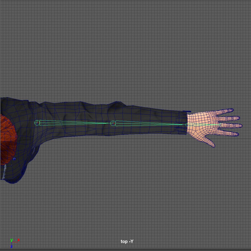
- Position Joints: Using the bony landmarks as a guide, translate each joint in the chain into the correct position. Use the up and down arrow keys step up and down the joint chain. Use the different camera views to check they are in the right place inside the mesh.
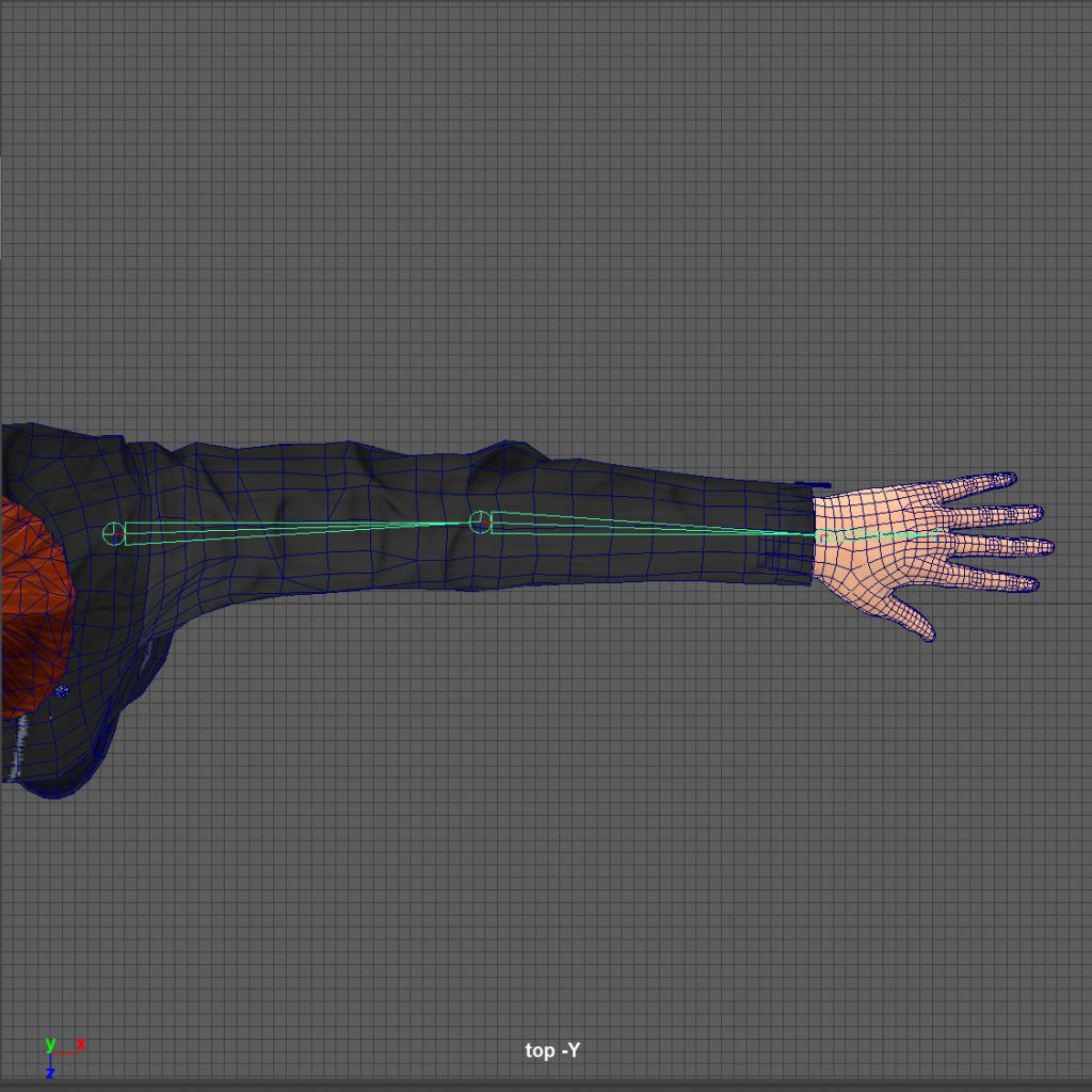
- Apply Skin Modifier: Once you’ve positioned the joints, skin them to the mesh using the default weight values. If you can get good results with the default skin weights, it will take less work to improve them later. Now rotate the joint to see if the movement and mesh deformation look believable.
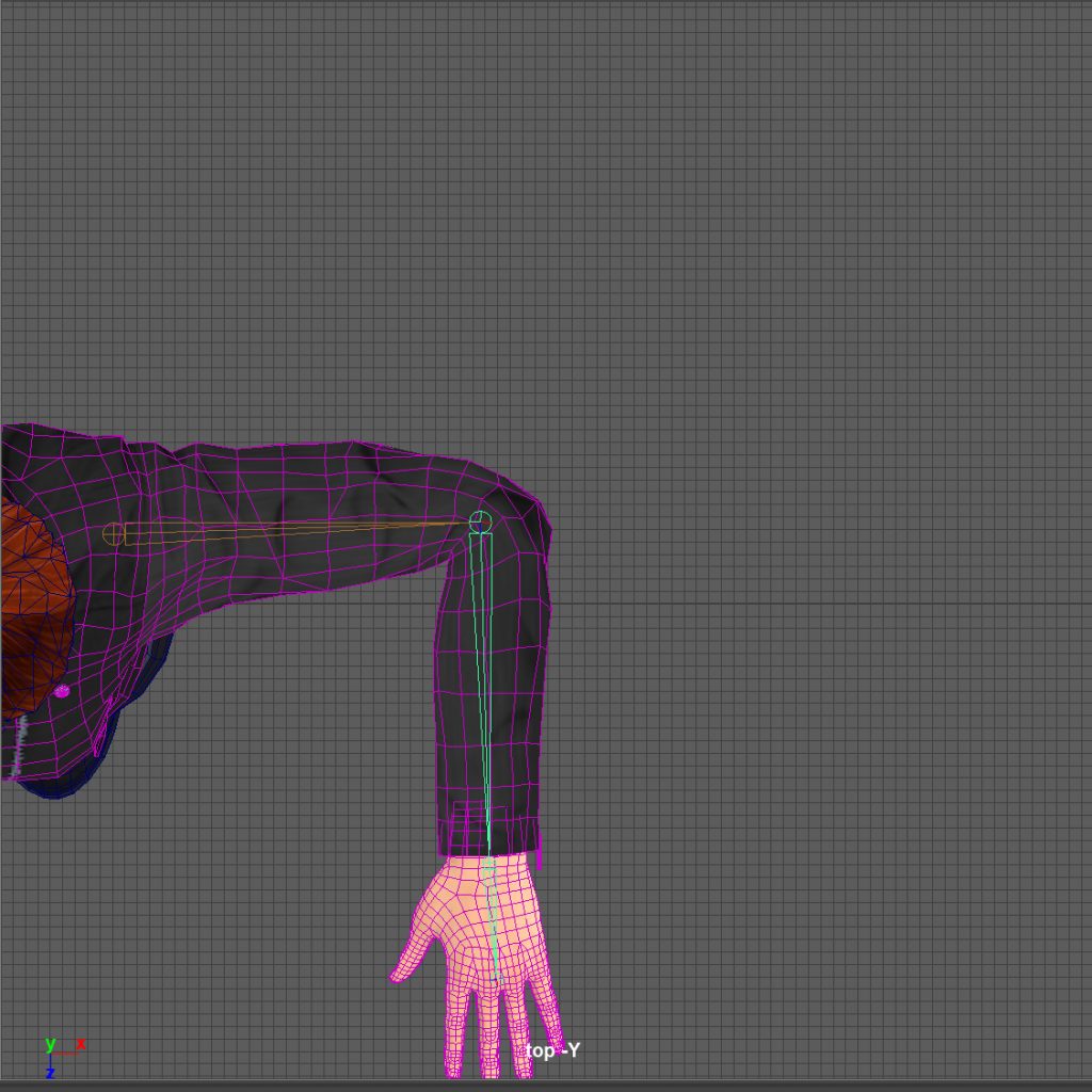
- Refine: If this position doesn’t work, remove the skin modifier, and adjust the joint position. Use the position where the joint rotates correctly as a starting point. Then adjust around that locations until you find the best deformation.
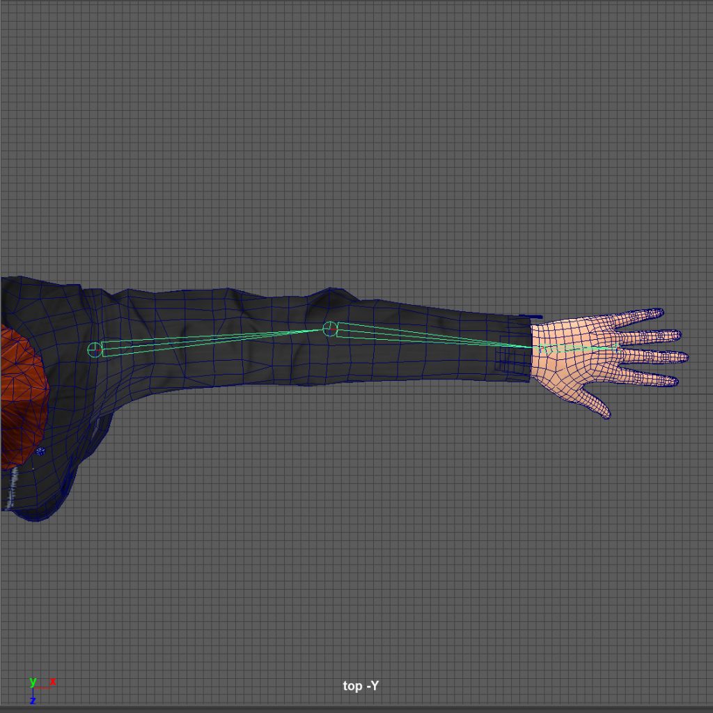
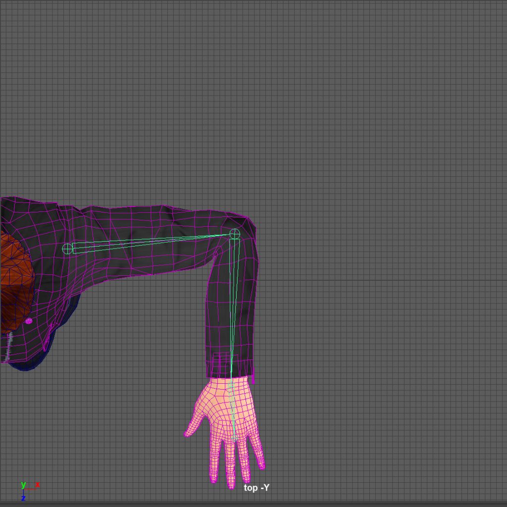
- Repeat: Repeat this process for each of joint in the chain. When all the joints are working correctly, move onto the next joint chain, and repeat the entire process.
Rebuild Joint Chains Cleanly
Once you have found the best position for every joint in the rig, it’s time to rebuild them with the correct settings.
Building and replacing joints almost immediately might seem like extra work, but it does make things easier. It lets you test ideas quickly without having to worry about naming conventions, joint orientation, and rotation orders, etc. Plus, when something is quick to build, it’s less painful to delete if it isn’t working.
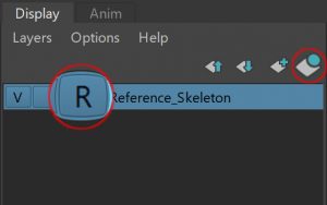
- Reference Joints: Select the root of the joint hierarchy and click “Create new layer and assign selected objects” in the Layer Editor>Display tab. Rename the layer and set it to Reference. Setting the layer to “Reference” lets you Point Snap the new joints to the existing ones without adding them to the hierarchy.
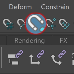
- Snap Joints to Reference Joints: With Point snap turned on, create a new joint by clicking on the existing reference joint in the perspective view. This will snap the position of the new joint to the existing one and build it with the correct transformation values.
- Alternatively…
- Build Joint Chain: In an orthographic view use Shift+Left-Click to create a horizontal or vertical joint chain. Then, translate the root or top node in the chain into the correct position. Only the root of the chain should have translation values in x, y, z. Every other joint should only have a single translation value along the axis aligned with the joint. In this example, X.
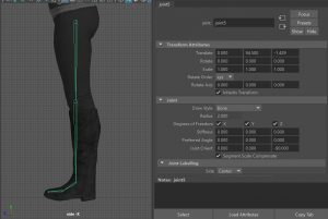
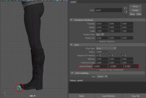
- Adjust Joint Orient Values: This time, rotate the joints into position by adjusting their Joint Orient values in the Attribute Editor. You can Ctrl+Middle-Mouse-Drag in the attribute box to change the value in a more interactive way. Rotating the joints in this way give them a Rotation Value of 0 (zero) in the Chanel Box. This lets you quickly reset them to a known or default position.
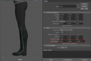
- Adjust Joint Length: If you need to adjust the length of the joint, translate it along the axis aligned down the joint (in this example, X). All the other axes should have a translation value of zero.
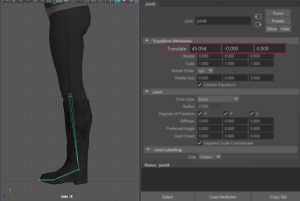
- DO NOT SCALE THE JOINTS. All joints must have a default Scale value of 1. Scale values can do funny things, especially once exported from the program they were created in. Always keep joint scale values set to 1.
- Zero End Joint: Reset the Joint Orient value of the last joint in the chain to zero. This will align it to the previous joint rather than the world.
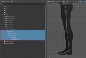
- Rename Joint: Using your joint naming convention, rename every joint in the chain as soon as you finish building it. It much easier to do it now rather than once everything is done, plus you’re less likely to miss a joint.
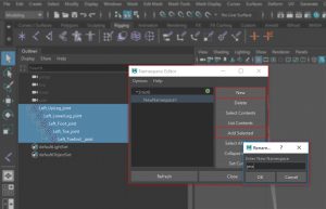
- Add Namespace: In the Outliner, select all the joints you’ve just created. Then in the Windows > General Editors > Namespace Editor click New. Double-click the “NewNamespace1” and change it to the name of your character. Finally, select the new namespace and click Add Selected. The namespace should appear in front of the joint name, separated by a colon “:”.
Set Joint Orientation
Joint Orientation controls how the joint acts when a rotation value is applied. It’s important to set this up correctly so your rig behaves in a predictable and consistent way.
The first thing to do is align one axis down the joint. This is called the Primary Axis in Maya. While you can choose any axis to be the primary one, MotionBuilder and some IK solvers prefer this to be X.
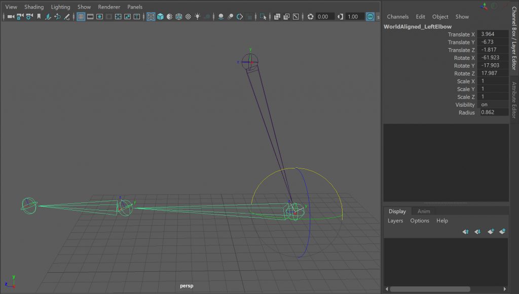
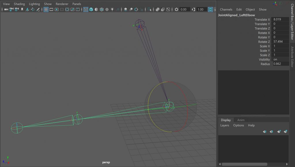
How does this help? Look at the 2 elbow joints below. One has axes that are world aligned, one has axes that are joint aligned.
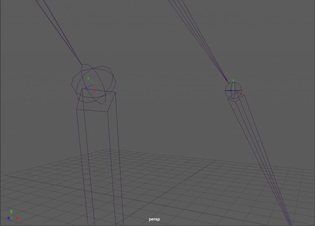
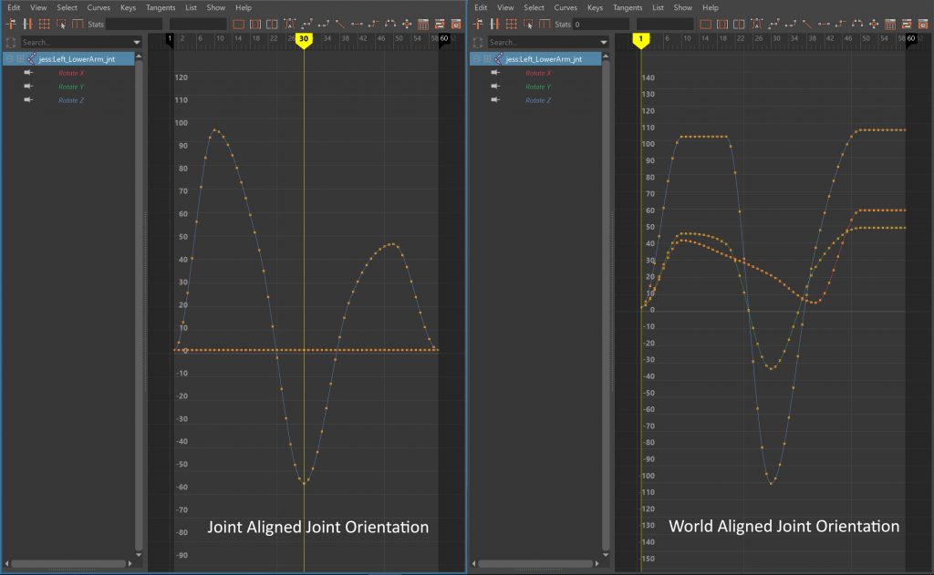
The elbow with the axes aligned to the world isn’t going to be easy to work with. You’ve got to rotate all 3 axes to get the joint into the correct position. This adds a value to each of the rotation channels, creating unnecessary key frames and FCurves you can’t understand. Not to mention the extra time and effort it takes to pose the joint.
However, the elbow with the axes aligned down the joint is much easier to work with. You only need to rotate it in Z. Using a single rotation axis means less key frames, less data to export and FCurves you can understand. Plus, if you need to find the length the joint, you can simply look at the value of the x-translation axis.
The next thing to do is align the secondary axis to the world so the joints rotate in a consistent way. Why? Imagine if you could look at the FCurves and know what your character was doing. Not like in the “Matrix”, but because you knew every time you saw a rotation in +z the joint was bending or curling (flexion). And every time you saw a rotation –z the joint was straightening (extension). Also, imagine how easy it would be to adjust all the joints in a chain if you only had to change one value. For example, scaling the rotate z key frame values on all the leg joints would curl them up higher during a jump. Or selecting all the finger joints in the hands and rotating them in +z would make a fist.
Suggested Joint Orientation
| Joint Name | Primary Axis | Secondary Axis |
| Hips | Y Down Joint. | Z World Orientation = +X |
| Spine | X Down Joint. | Z World Orientation = +X |
| Arms | X Down Joint. | Z World Orientation = -Y |
| Hands and Fingers | X Down Joint. | Z World Orientation = -Z |
| Thumb | X Down Joint. | Z World Orientation = -Y |
| Legs | X Down Joint. | Z World Orientation = +X |
To set the orientation of a joint:
- Select Root of Joint Chain: Select the root of the joint chain you are going to align.
- Orient Joint Options: from the Skeleton>Orient Joint menu, open the Orient Joint Options window.
- Set Primary Axis: In the Orient Joint Options window set the Primary Axis to X.
- Set Secondary Axis: In the Orient Joint Options window set the Secondary Axis based on the table above.
- Set Secondary Axis World Orientation: Again, using the table above as a guide, set the Secondary Axis World Orientation. This specifies which world axis the second orientation axis should align with.
- Apply: Check “Orient children of selected joint” is turned on and click “Apply”. This will orient all the rotation axes of the joint chain. You can see the results of this by selecting all the joints in the chain and clicking “Toggle Local Axes Visibility” in the “Orient Joint Options” window.
How you align the joint axes is down to personal preference or the project you are working on, but the result should always be the same: joints should always rotate in a consistent way.
Set Joint Rotation Order
Finding the best Rotation Order for the joints in your rig is one of the most important things you can do.
In 3D software, the Rotation Order is literally the order in which the rotation values of an object are evaluated. This can have a massive effect on the final position of the joint and the way it interpolated between key frames. For example, the Hips on the character below have a default rotation order of xyz.
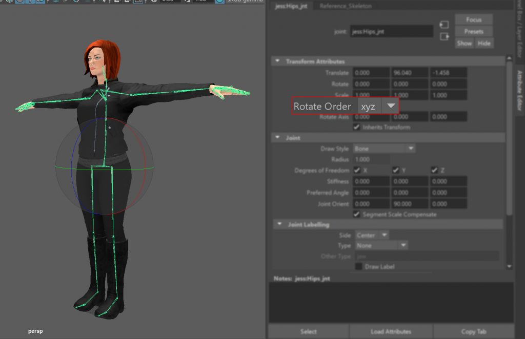
Using the Rotation tool (e) with the Axis Orientation set to Gimbal, you can bend the character forward in X, turn it around in Y and lean it side to side in Z. But if you rotate the character around the Y axis, by 90°, the x axis aligns with the z axis. The problem now is, you have no axes available to lean the character to the left or right. You have now entered what is commonly known as Gimbal Lock.
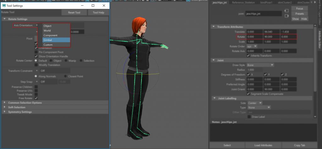
The only way you can lean the character forward is to switch the Axis Orientation to “Object” and rotate the hips. The problem with this is, as you rotate the character all the rotation axes change. And if you apply a key frame you get some very strange results in the FCurve editor. Suddenly you cannot tell what the hips are doing by looking at the FCurves. Sometimes z is forwards and backwards, and sometimes it’s side-to-side.
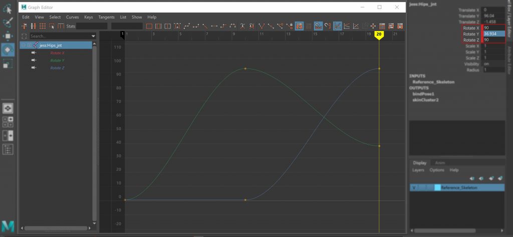
Before you go setting any Rotation Orders, the first thing to understand is that they are calculated in reverse order. For example, when the rotation order is set to xyz, the z axis will rotate the y and x with it. The Y axis will rotate the x axis. And finally, the x axis will only effect itself.
So, when setting the rotation order, the most important axis – the one you want the other axes to follow – will be last in the order. And the least important axis – the one that will only effects itself – will be first.
Now you know how the rotation order is calculated, you need to decide which one to use for each of the joints.
The easiest way to do this is to describe what action each axis is actually doing. Then order those actions from least to most important, based on how often your character will do them.
Using the Hips as an example:
- X = Bends forward and backward
- Y = Turns around
- Z = Bends side to side
Now you can try to use these descriptions to figure out which axis is most important or which actions your character it’s going to be doing the most.
- Turning around the most = Y
- Then, bending forward and backwards = X
- Finally, bending side to side = Z
So, in this case the winning Rotation Order is ZXY (as a rule, anything rotating in world space usually uses a rotation order of zxy or xzy)
You can now use this idea to work out the rotation orders for the rest of the joints. Always test how well the rotation order works using the Gimbal or Additive rotate tool.
To help get you started, here are some suggested Rotation Orders. These have the X axis aligned down joint and bend or curl in +Z:
Suggested Rotation Orders
| Joint | Rotation Order |
| Hips | xzy |
| Spine | xyz |
| Head | yzx |
| Shoulder | xzy |
| Upper Arm | xzy |
| Lower Arm | xyz |
| Hand | yxz |
| Fingers | xzy |
| Upper Leg | xyz |
| Lower Leg | xyz |
| Foot | xyz |
| Toes | xyz |
Although MotionBuilder has tools to deal with gimbal flips, these often “hide” the lock or flip at a sub frame level. While this enables the animation to playback correctly, it may produce unexpected results if you need to use anything at the sub-frame level like rescaling the animation or motion blur.
ROTATION ORDERS ARE ONE OF THE MOST IMPORT THING TO GET RIGHT ON YOUR RIG
Set Degrees of Freedom (DOF)
Setting the Degrees of Freedom (DOF) lets you limit how much a joint can rotate in the x, y and z axes.
These setting are typically used to restrict the rotation of the elbow and knee joints to one axis. This stops them rotating in impossible ways and reduces the amount of key frame data they produce.
If you are going to set the DOF for a joint, there are a couple of things you need to check to make sure your rig will still solve correctly:
- One of the rotation axes must be aligned with the joint. If you set your joint orientation in the previous steps this should already be correct.
- The roll axis should be the first axis in the Rotation Order you have set for the joint. If you set the Rotation Orders in the previous step, this should also be correct.
- If you limit the DOF for the roll axis, you will need to use a roll bone or remove the DOF for all three axes on the wrists and ankles.
Add Roll Bones
Roll bones are used to help improve the way the mesh deforms on limbs that twist, for example, the forearm.
They work by dividing the amount of twist along several individual joints in a chain. This helps improve the skinning by spreading the twist evenly along the mesh, reducing what is sometimes called the “Christmas Cracker Effect”. It also creates an effect similar to the way real bones and muscles affect the skin.
The bad news is, MotionBuilder only supports one Roll Bone per limb segment. This means to get the best results, you will need to create a separate Roll Bone set-up or deformation rig. The good news is, because the MotionBuilder rig won’t contain any roll bone rigging, it will be light enough to drive a more complex rig that does.
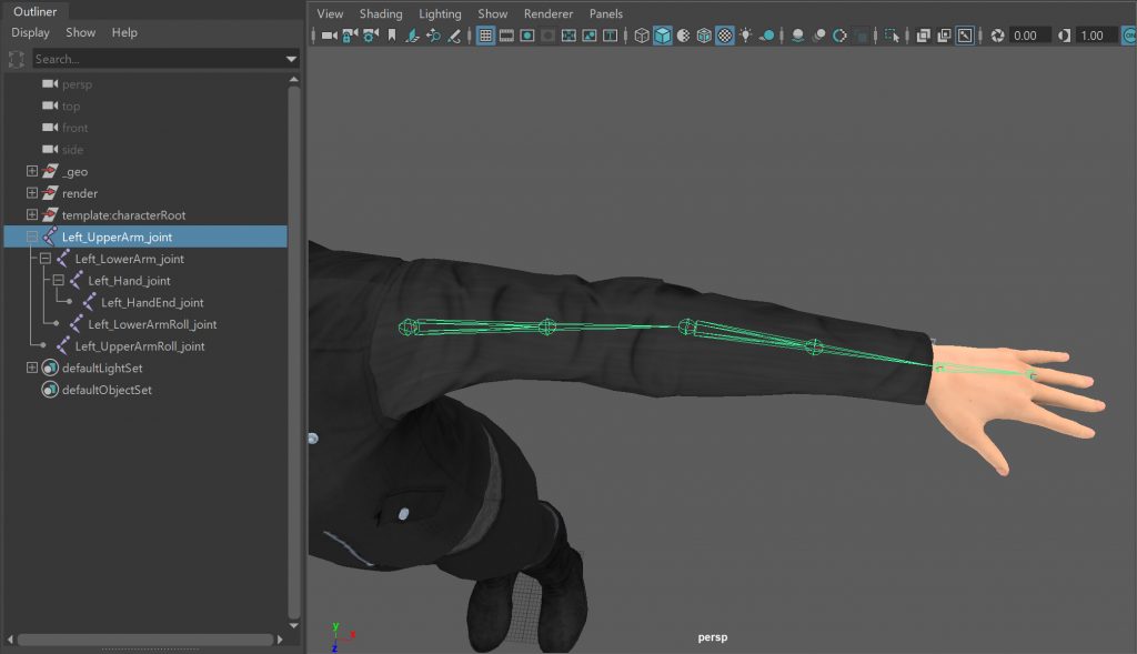
If you do want to add roll bones into your rig, they need to be a child of the previous joint in chain. For example, the RightForeArmRoll must be a child of the RightForeArm. However, the roll bones do not need to be the parent of the following joint in the chain. For example, LeftArmRoll does not need to be the parent of/connected to LeftHand. The good thing about this is that it makes them easy to remove or ignore if you need to. For example, if you want to find the length of a joint or apply procedural IK to the arm or leg.
- Duplicate Joint: Duplicate (Ctrl+D) the joint that will be the parent of the roll bone. For example, the Upper Arm, Lower Arm, Upper Leg, or Lower Leg. This creates a joint with the same setting and position as the original.
- Re-Parent: Re-parent the roll bone to joint you use to create it. Left-Click the “child” roll joint, Shift+Left-Click the “parent” joint, and then press “p”.
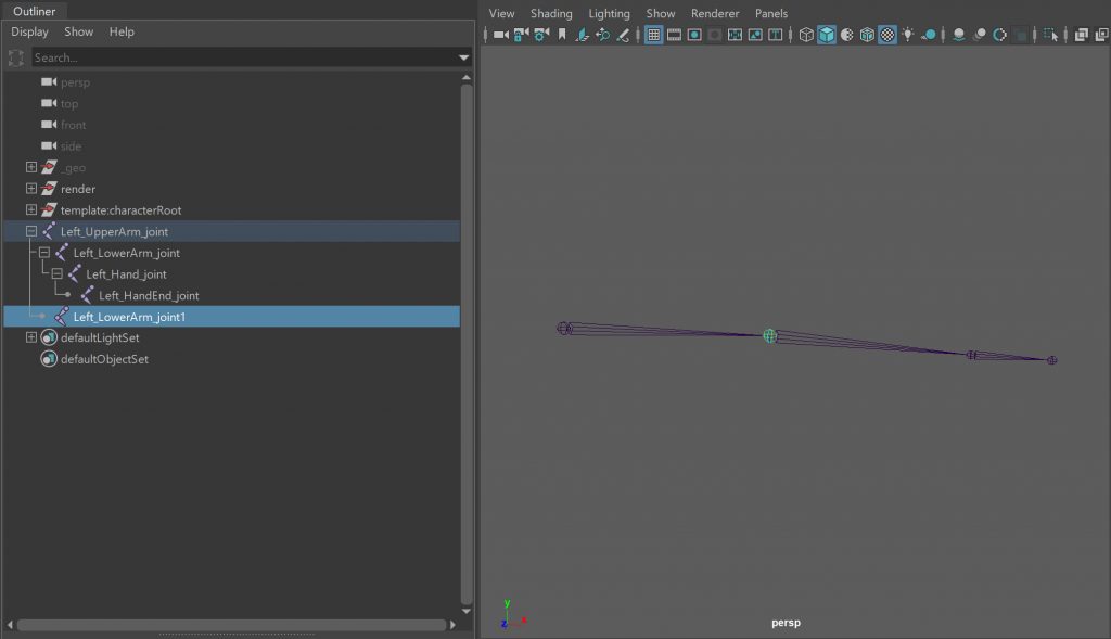
- Delete Other Joints: As you only need the duplicated joint, you can delete all the other joints. You may also need to Unparent the joint if it isn’t the root of the joint chain.
- Re-Position: Translate the roll joint into the correct position. USE TRANSLATE X ONLY
- Rename: Rename the roll joint to something more descriptive based on your naming convention.
Mirror Arms and Legs
The Mirror Tool creates a symmetrical copy of a joint chain across a selected plane.
Most 3D packages have a tool for mirroring joints correctly. This is useful when you’re building the limbs for your character. It means once you’ve built the limbs for one side of your character, you can mirror them to create the opposite side. DON NOT duplicate the joints with a scale value of -1. This is very bad and rarely works outside the program you are doing it in.
One thing to note, if your mesh isn’t symmetrical the joints won’t be mirrored in the correct position. You can still use the mirror tool, you’ll just need to adjust the position of the joints once they’ve been mirrored.
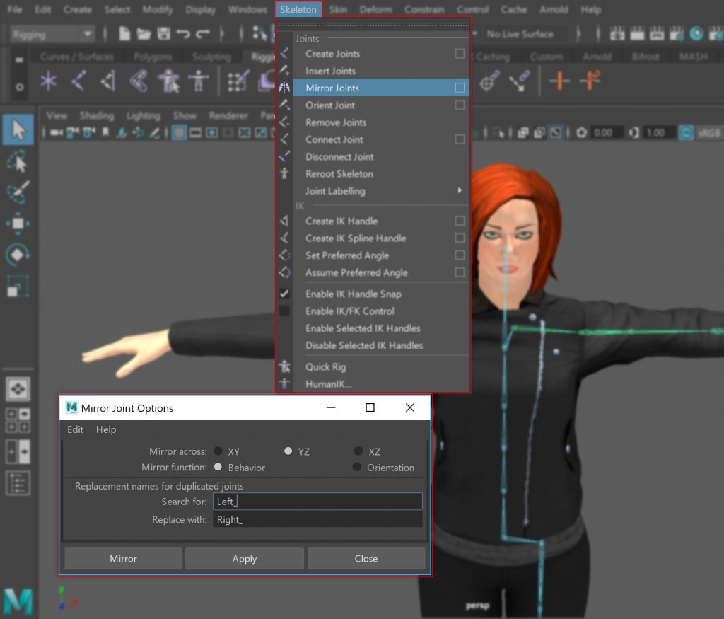
- Select Root: Select the root or top joint of the chain you are going to mirror. For example, the clavicle/shoulder or upper leg.
- Open Mirror Joint Options Window: From the Skeleton menu, open the options for the Mirror Joints tool.
- Mirror: In the Mirror Joint Options window, there are usually options for setting the mirror axis, mirror function and joint renaming. The following are suggestions to get you started:
- Mirror YZ: Set the tool to mirror the joint chain over the YZ plane.
- Mirror Behaviour: Mirror the behaviour of the joints so you can rotate the limbs in the same direction simultaneously. For example, rotating both upper arms in +Y the character will put their arms up and rotating them in +z the character will reach forwards.
- Rename: Change the side token in your joint names to use the opposite side. For example,
- Search for: “Left_”
- Replace with: “Right_”.
Parent Everything into Single Hierarchy
The final step is to parent all the joint chains together into a single character hierarchy grouped under one node.
Not only does this help keep your scene neat and tidy, it also makes it easier for people find what they need. For example, grouping the geometry and joint objects into separate hierarchies means someone looking for a joint doesn’t have dig through all the geometry elements as well. Very handy if your character is made of lots of individual pieces of geometry. Also, grouping everything under a single node makes it very easy to find everything that belong to that character. Perfect when your scene contains multiple characters and you want to find something belonging to it.
- Parent Character Together: Parent all the separate limbs of the character together
- Spine to Hips
- Legs to Hips
- Shoulders to Chest
- Neck to Chest
- Finger to Hands
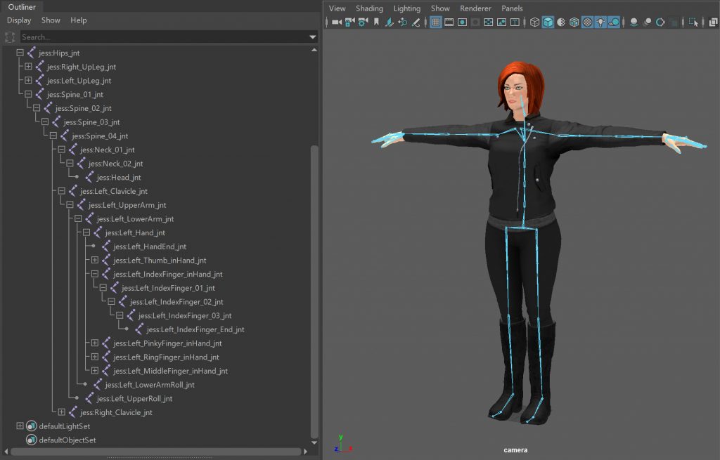
- Parent Hips to Reference: Create a null object at the centre of the scene and rename it to “Reference”. Change its rotation Order to ZXY. Then parent your characters “Hips” to the “Reference” null. This Reference node will be used in MotionBuilder to globally transform the character.
- Group Joint Objects: Select the Reference null and create a Group (Ctrl+g) Rename the group to “mocapSkeleton”
- Group Geometry Objects: Select all the geometry objects and add them to a Group (Edit>Group). Rename the group to “geo”.
- Group mocapSkeleton and geo: Select the “mocapSkeleton” and “geo” groups and create a Group. Rename the group to “MocapRig”.

Skin Character
Now all the joints have been built and tested, it’s time to skin the character.
Both rigid and smooth skinning are supported in MotionBuilder. Any additional rigid geometry can be parented to the appropriate joint. For example, hair and eyes.
As skinning is something of a project on its own, I’m not going to cover it here. I used ngSkinTools for this character. Their website has some excellent starter videos to get you started.
Export FBX
Once your character is rigged it’s time to export it to MotionBuilder.
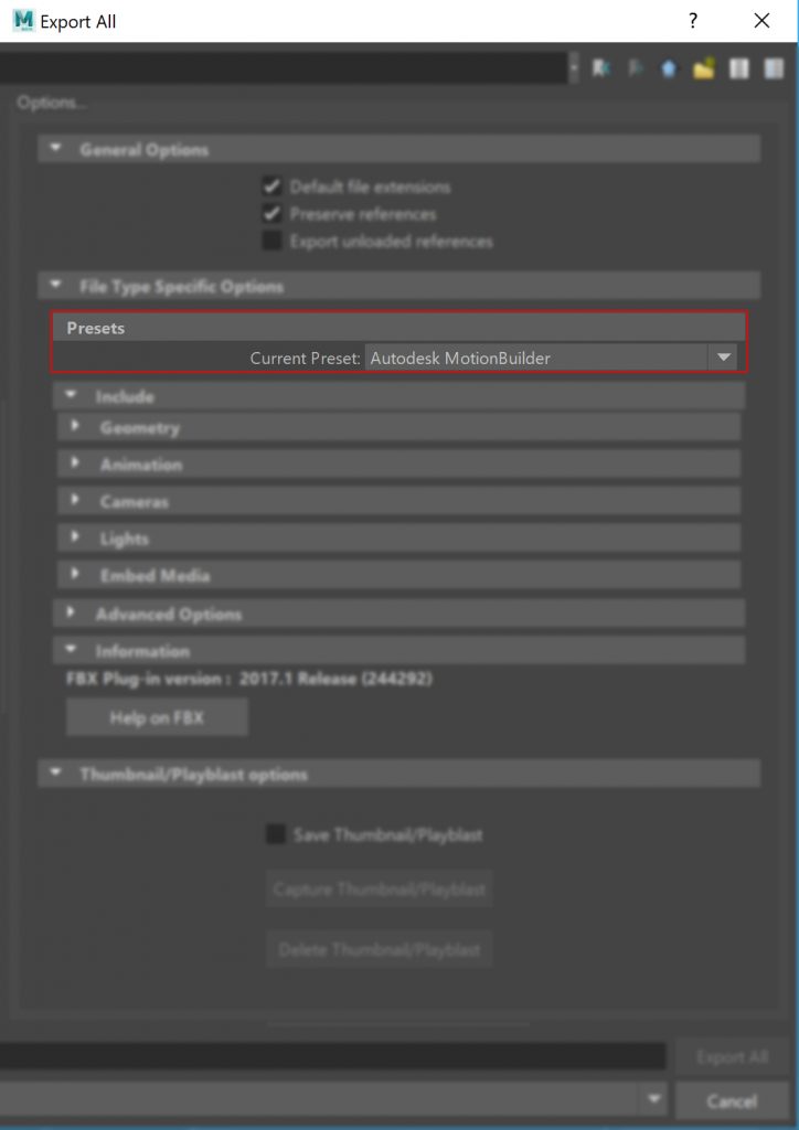
For this example, you can use the default “Autodesk MotionBuilder” pre-set to export your character to MotionBuilder as it is designed for a Maya <> MotionBuilder workflow. The “Constraints” and “Skeleton definitions” options are selected to make sure all supported constraints (Point, Aim, Orient, Parent, IK) and Skeleton definitions (FBIK/HumanIK) are exported.
To learn more about the export options, check out the help docs to see what options and elements are supported by the plug-in you are using.
- Maya 2017 http://help.autodesk.com/view/MAYAUL/2017/ENU/?guid=GUID-BD85FA4C-4D40-457C-BE66-47BC08B82FC3
- Maya 2016 http://help.autodesk.com/view/MAYAUL/2016/ENU/?guid=GUID-BD85FA4C-4D40-457C-BE66-47BC08B82FC3
- Maya 2015 http://help.autodesk.com/view/MAYAUL/2015/ENU/?guid=GUID-BD85FA4C-4D40-457C-BE66-47BC08B82FC3
- Maya 2014 http://download.autodesk.com/global/docs/maya2014/en_us/files/GUID-BD85FA4C-4D40-457C-BE66-47BC08B82FC3.htm
- 3DS Max 2017 http://help.autodesk.com/view/3DSMAX/2017/ENU/?guid=GUID-EB0F5BB7-2E59-4EF6-8B16-F59CC56A4747
- 3DS Max 2016 http://help.autodesk.com/view/3DSMAX/2016/ENU/?guid=GUID-EB0F5BB7-2E59-4EF6-8B16-F59CC56A4747
- 3DS Max 2015 http://help.autodesk.com/view/3DSMAX/2015/ENU/?guid=GUID-EB0F5BB7-2E59-4EF6-8B16-F59CC56A4747
- 3DS Max 2014 http://help.autodesk.com/view/3DSMAX/2014/ENU/?guid=GUID-EB0F5BB7-2E59-4EF6-8B16-F59CC56A4747
Lock Skeleton
Finalise the joint names and most importantly the joint positions BEFORE you process any mocap data with it.
Changing the position, orientation or rotation order of a joint will severely affect the quality of the final data or leave it completely unusable. If a joint in MotionBuilder has a different name to the corresponding joint in your 3D software, the importer will ignore it. The animation data from the MotionBuilder will not be applied and the joint and its children will remain motionless – this is often the first thing to check if your import fails.
When your character is set-up in MotionBuilder, apply some key-frames to it and export the data back onto your target character. Always check the character pipeline is working correctly before you capture any motion.
Export Character
- Load fbxmaya.mll plug-in: From the Windows>Settings/Preferences open the Plug-in Manager. Sometime the plug-in may not have loaded when Maya opened.
- Export All… As your scene only contains a single character, the entire scene can be exported as an FBX file using File>Export All…
- Set File Path: Navigate to the folder where you want to save the file.
- Select FBX export: At the bottom of in the export dialogue window select “FBX export” from the “File of Type menu. If you don’t see the “FBX export” file extension, you will need to activate the fbxmaya.mll in the Windows>Settings/Preferences>Plug-in Manager.
- Set File Name: Name the file something descriptive and include a version number. For example, <CHARACTER_NAME>_mayaExport_v001.fbx. This way you know which character is in the file, what the file is and which version it is at.
- Use Autodesk MotionBuilder Preset: Use the “Autodesk MotionBuilder” pre-set options to export your character to MotionBuilder.
- Export: Finally, click Export in the export dialogue window
- Errors vs. Warnings: If there are any errors during the export process, a “Warnings and Errors” window will appear at the end. There is a difference between “Errors” and “Warnings”:
- Errors occur when something unexpected happens. It shows the results of the error are unknown.
- Warnings tell you the plug-in has converted the source data into a format MotionBuilder can understand.
Conclusion
Every studio, project and character will present their own set of rigging challenges you will need to overcome, but the aim is always the same; build a rig that produces accurate, high quality data in a clean, simple and consistent way.
This, along with the rest of the posts on your site, has been a great reference for me as i ramped up on Mobu. Pertaining to this article, could you cover how to handle/prep a character model that comes to you in A-pose, “huggy bear” pose or any non-standard non T-pose?
Hi Brobot,
Great to hear you find the site useful.
For a character in an A-Pose or non-T-Pose, you can work in exactly the same way. Build the test joints in a straight line and then rotate or translate them into the correct positions for the lowered shoulders and bent elbow. Test the joint positions for motion and skinning. Then Rebuild the joints chains cleanly in exactly the same way as you would if they were in a T-Pose.
Hope this helps,
Simon
Hello,
your homepage has a lot of great information and is very helpful to understand the workflow.
do you have any experience rigging for motionbuilder in houdini?
or any exoerience with houdini/motionbuilder workflow?
thank you for your great work.
Hello,
Thanks for taking the time to leave a comment!
I don’t have any experience ringing in Houdini I’m afraid. However, the workflow I describe in this post is the same in any 3D package, you just have to find the buttons, menus and option for that piece of software.
In terms of workflow, I’m pretty sure Houdini imports/exports FBX files and I think it also reads HTR if you only want skeleton animation files.
Hope this helps
Hi,
I may not have used your website for the intended purpose of it but the anatomical structures surely helped me for studying my exams in uni. It’s detailed, useful and what I’m really looking for. Love the art, science and technology mash up!
Thanks!
Hi,
Amazing! Thank you. You may not be the target audience, but I’m loving the fact it’s helped with your studies.