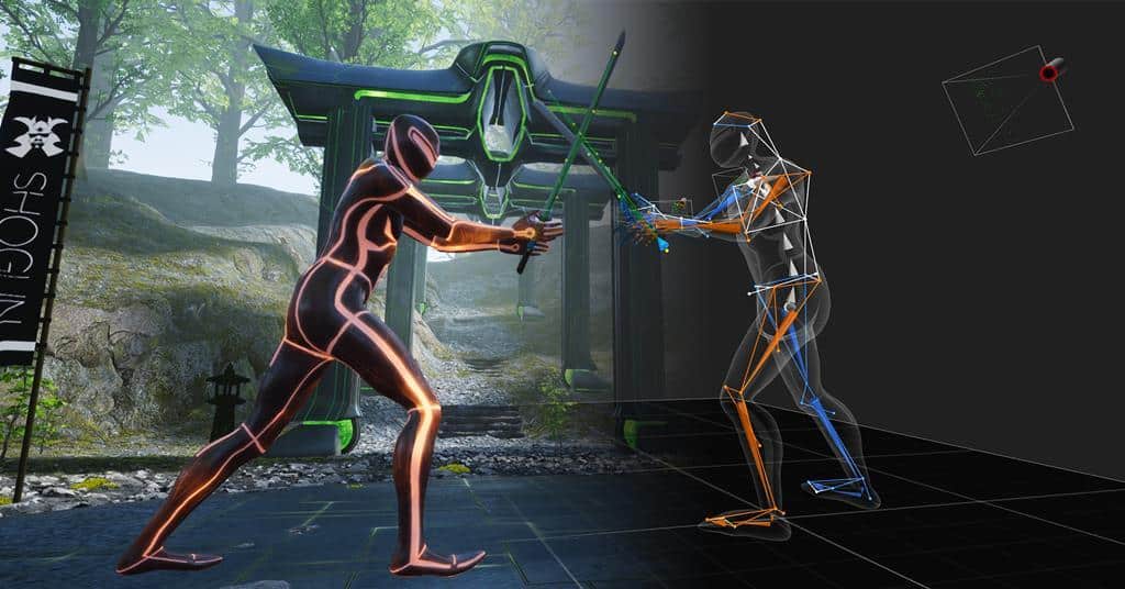
Introduction
In this guide we’ll look at how to use a Vicon Motion Capture System to mocap a performer.
We’ll cover everything from calibrating the cameras and configuring the mocap volume, to capturing and reviewing a take in Shogun Live. Plus, all the tips and tricks you’ll need to capture the best data possible – and if you want to learn more what happens after a shoot, here’s an overview of a Post Performance Capture Pipeline.
At each stage of the process I’ll try and explain how a Vicon system, and optical systems in general, work, so you’ll have a better understanding of what you’re doing and why you’re doing it. Handily, this also means a lot of the information will also apply to other optical systems like Motion Analysis and OptiTrack – If you want to learn what happens after the shoot, here’s an overview of a Post Performance Capture Pipeline.
Last but not least, this assumes you already have the cameras mounted and aligned because, that’s a whole other guide in itself…
Before you Begin
There are a couple of things you can do before you even calibrate your system that will help improve the accuracy and quality of your mocap data.
Warm up Cameras
Before you do anything else, TURN THE CAMERAS ON.
As things heat up, they expand. The cameras contain lights and on-board processors which all generate heat. Even the mounting system for your cameras can expand as the room heats up. And when you’re mocap system measure distances to less than a millimetre, you need to make sure everything has stopped expanding as much as possible BEFORE you calibrate your system.
When you calibrate an optical mocap system, the exact position and rotation of each camera is calculated by the system. It then uses this information to triangulate the position of each marker in the volume with submillimetre accuracy. So, if a camera moves after it’s been calibrated, even by the tiniest amount, it will generate errors in the calculations and reduce the accuracy of your data.
Vicon recommends running the system for at least 30–60-minutes so it can reach a stable operating temperature. To help speed things up, you can also run Vicon Shogun Live software and make sure the camera strobes are active.
This should give you just enough time to play “hunt the shiny thing”.
Remove Reflective Objects
An optical mocap system works by emitting infra-red light from a ring of LEDs around the lens of each camera. This light is reflected back to cameras by the retroreflective (passive) markers.
If there are any reflective objects or surfaces in or around the capture volume, they will reflect the light in exactly the same way, making it difficult for the system to distinguish what is and isn’t a marker. Items like stray markers, high visibility patches on running shoes or clothing, polished metal or glass surfaces, monitor screens, even infrared lights for a camera’s auto-focus will all need to be removed, hidden or covered, before calibration.
To help you find these objects in your capture volume, they are displayed as red and white pixels in the Camera views in the Shogun Live software.
Set Capture Frame Rate
The first thing to do in the software is set the capture frame rate. This is the number of frames per second (FPS) the system will capture and calculate the position of the markers in the volume.
Ideally, you should be capturing data at a frame rate that is a multiple of your final delivery frame rate. For example, if you’re delivery frame rate is 24fps, then capture at 48, 72, 96, 120, etc. If your delivery frame rate is 30fps, then capture at 60, 90, 120, etc. You may have noticed one number is available in both options, and that’s 120.
120fps is a good frame rate to capture at as it offers the most compatibility. There are other factors that will affect the system’s ability to capture at this frame rate, but as a rule, 120fps is a good frame rate to start at.
In Vicon Shogun Live, under System Panel>Frame Rate (Hz), set the Frame rate to 120.00.
Calibrate Cameras
Once the cameras have reached a stable operating temperature, you can calibrate them.
Camera Calibration usually involves 4 main steps:
Mask Cameras
Any reflective items that cannot be removed from the volume must be “Masked” from the cameras view.
Creating a “Mask” tells the system to ignore the information from a specific part of the camera view. Unfortunately, this also means anything entering this area will also be ignored. So be careful, the more of the camera view you “Mask” out, the less the camera can see. And if enough cameras cannot see a marker, it cannot be captured.
Once masking is complete, blue pixel masks are drawn over the reflective objects in the Cameras views. This will show you how much of the camera view has been masked. Ideally you want the camera view to be completely black or have as few blue pixels as possible.
Set Greyscale Mode
Before masking the cameras, set the Grayscale Mode for all cameras to Auto.
- In the System panel, select all the cameras.
- In the Optical Setup section, set Grayscale Mode to Auto.
Auto Masking
- In the Load Saved View list, click System Setup to show the panels needed for calibration.
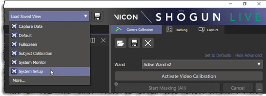
- In the System panel, select all the cameras, including any video cameras connected to your system.
- In the Camera Calibration tab, check Slack (pixels) is set to at least 1. This creates a 1-pixel border around the object being masked. If it looks like the object will move or grow in size, increase the Slack value to make sure it remains covered.
- Click Start Masking (All). The text on the button will change to Stop Masking and Auto Mask Active is displayed at the top of the workspace.
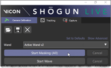

- After about 5–10 seconds, when t he system has collected enough data and masked all the reflections, click Stop Masking.
- Check all the reflections (red pixels) have been masked with blue pixels in each of the Camera’s views. The camera view should be completely black or show some blue “mask” pixels.
Apply Additional Masking
- In the System Panel, select the camera to apply additional masking.
- In the Camera Calibration tab, turn on Advanced Options.
- Deselect the Clear Previous Masks check box.
- In the Cameras To Mask list, choose Selected Cameras Only. This will only apply the new masking to the selected cameras.
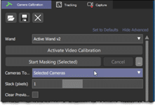
- Click Start Masking. Auto Mask Active is displayed at the top of the workspace.
- When masking is complete, click Stop Masking. New blue “mask” pixels should be visible in the camera view.
Manual Masking
- In the Camera Calibration tab, click Start Manual Mask Paint. Manual Mask Painting Active is displayed at the top of the Workspace.
- Use the following shortcuts to select and mask:
- Apply masking = Alt+E or click the pencil icon next to the pin button.
- Apply masking = Alt+E or click the pencil icon next to the pin button.

- Erase masking = Alt+R or select the masked area and click the eraser button.

- Click Stop Manual Mask Paint when complete.
Capture Wand Wave
The next step is to calibrate the camera positions using the Calibration Wand.
The calibration wand is “T” shaped with 5 pairs of LED lights set at specific distances along the wand. When the wand is moved through the volume, the system uses the position of these markers to calculate the focal length, lens distortion, and position and rota tion of every camera in the system.
| IMPORTANT After the wand wave calibration process is complete, the cameras may be shown at the wrong angle compared to the floor grid in the software. This is normal and will be corrected when you “Set the Volume Origin” in the next step. Once the calibration is complete DO NOT MOVE THE CAMERAS. If a camera gets knocked or bumped, changing its position even slightly (remember, the system is submillimetre accurate) it’s usually a good idea to recapture the Wand Wave calibration. It is also a good idea to calibrate the system at least twice during a full day shoot: one in the morning before the shoot and one before the afternoon session starts. If the shoot is only a couple of hours, a single calibration will be OK. |
- Make sure Active Wand V2 is selected in the Wand list at the top of the Camera Calibration tab.
- Click Start Wave to start collecting data and begin the calibration process. The text on the button will change to show Stop Wave and Camera Calibration Active will be displayed in the menu bar next to a flashing red circle.
- Wave the wand through the capture volume, making sure to cover or “paint” as much of each camera view as possible. Make sure to cover from the centre to the edges, and from the floor to the top of the volume. Try to keep the markers on the wand visible to as many cameras as possible during the wand wave calibration.
- During the wand wave, the data captured from the wand will change from orange to blue in the camera view to show enough data has been collected.
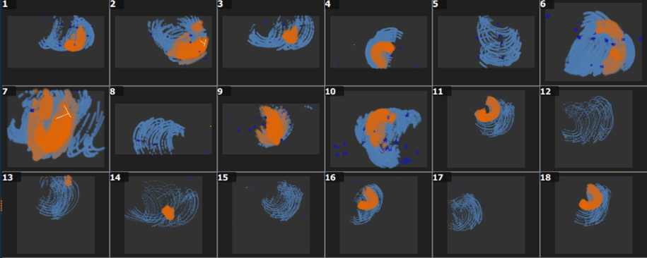
- In the table at the bottom of the Camera Calibration tab, the Wand Count column will change from red to green for each camera to show enough data has been captured.
| TIP By default, the camera calibration will stop automatically when enough data has been received from all the cameras. To adjust this or turn it off, at the top right of the Camera Calibration tab, click Show Advanced and then click the ellipsis (…) to the right of the Start Wave button. To adjust this or turn it off, at the top right of the Camera Calibration tab, click Show Advanced and then click the ellipsis (…) to the right of the Start Wave button. |
- The status light on the camera body will change from flashing magenta to green and finally blue when fully calibrated. The OLED screen on the camera also displays a pie chart to shows how much wand data the camera has been received.
- In the Image Error column, Shogun Live grades the calibration status of each camera between red (poor) and green (excellent), depending on how much the cameras see the wand.

- When enough data has been collected, Shogun Live stops collecting and starts processing it.
- If a camera has not captured enough data to give a good calibration, a warning will be shown in the Log. The warning will show the camera User ID and URN.

- When the calibration is finished, an .xcp and.x2d file is created in C:\ProgramData\Vicon\Calibrations. If your calibration included Vicon video cameras, two x2d files will be created:
- LatestCalibration.x2d – the wand wave without any Vicon video cameras
- LatestCalibration_withVideo.x2d – the wand wave including Vicon video cameras.
| NOTE After a wand wave, Vicon video cameras do not produce video files as they are not needed for calibration. After the wand wave calibration process is complete, the cameras may be displayed at the wrong angle relative to the floor grid. This is normal and will be corrected in the next step when you “Set Volume Origin”. |
Set Volume Origin
Now the cameras know where they are relative to each other, you need to set them relative to the space you are capturing in. To do this, you will use the Calibration Wand.
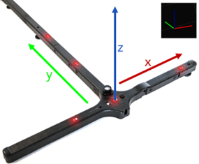
Setting the Volume Origin (centre) tells the mocap system where the centre or origin of the volume is (0, 0, 0,). It also sets the global coordinates system for the capture space and direction of x, y, and z, so everything is displayed and captured the right way around.
| TIP Make a note of which direction positive (+) Y points (the handle of the wand). You might need to capture actions facing or moving along a specific axis or be asked which direction is “forward”. |
- In the Workspace tab, change the view to 3D Scene and Perspective. This will display the Floor Grid and Global Axis in the corner of the screen (View Filters>Volume and Overlay respectively).

- In the 3D Scene, click View Filters. Under the Volume options, select Cameras (don’t worry if they don’t look correct, we’re about to fix this).
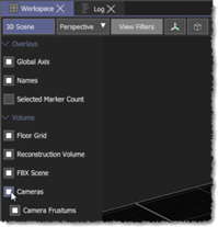
- Place the calibration wand in the position you want the centre or origin of the volume to be.
- Align the handle of the wand in the direction you want positive (+) Y axis to point (make a note of this).
- Exit the capture volume to make sure all the cameras can see the calibration wand.
- At the top of the Camera Calibration tab, in the Wand list, make sure Active Wand v2 is selected.
- Click Start Set Origin. The text on the button will change to show Set Origin.
- After a few seconds click Set Origin.
- All the cameras should jump into the correct position and the origin of the capture volume should be aligned with the wand.
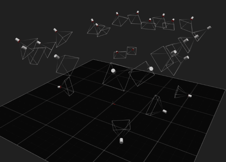
Set Floor Plane
The final step is to set the floor plane of the capture volume.
When you Set Volume Origin, the software uses the alignment of the wand to calibrate the floor plane. If the wand isn’t perfectly level for any reason, the capture floor will be on a slope. Also, because the wand is very small compared to the size of the floor area, it is only measuring a tiny spot which may not match the overall angle of the floor.
To correct this, the angle of the floor plane can be measured using a much larger sample of the floor area. This will make sure the floor plane in the software aligns with the actual floor plane in the studio.
- Remove the calibration Wand from the volume.
- Place a minimum of four markers in each corner of the capture floor area.
- If you are not using 14mm markers:
- Click Show Advanced.
- Click the ellipsis (…) next to Start Set Floor Plane
- Change the Height offset to the correct value to match the markers you are using. The Height offset is the height in mm from the base of the marker to the centre of the marker sphere (the software calculates the centre of the marker).
- On the Camera Calibration tab, click Start Set Floor Plane. The text on the button will change to Set Floor Plane.
- After a few seconds, click Set Floor Plane.
- The LatestCalibration.xcp in C:\ProgramData\Vicon\Calibrations is updated.
| TIP To help you visualise the size of the capture volume in Shogun Live, you can change the size and shape of the floor grid: 1. In the Camera Calibration tab, click the ellipsis (…) next to Set Floor Extents. 2. Change the Min and Max values (in mm) to match the size of the floor area (the distances in the software are measured from the centre to edge of the floor). |
Create a Subject
A capture subject in this example, is the performer or performers that are going to be captured, but they can also include props or cameras.
Before a subject is created, the mocap system can only see individual markers moving around in space. It doesn’t understand what the markers are attached to or how they relate to each other. To help it understand this, you need to create and calibrate a subject.
Creating a subject tells the mocap system how a particular group of markers relate to each other and what they are tracking. The calibrations process teaches the system how these markers move relative to each other.
Once the system understands all this, it can use the information to identify and track the subject in the volume.
There are 5 main steps to creating a subject:
Choose a Marker Set
To allow the system to automatically identify and label the markers on a performer, one of the following Marker Sets must be used:
| Marker Set | Description |
|---|---|
| FrontWaist | Standard 53-marker set |
| FrontWaist10Fingers | Standard marker set plus 10 finger-markers |
| FrontWaist3Fingers | Standard marker set plus three finger-markers |
| FrontWaist5Fingers | Standard marker set plus five finger-markers |
| Production | 57 Markers. Includes additional markers on back and shoulders to help with occlusion, gap-filling and solving. |
| Production10Fingers | Production marker set plus 10 finger-markers |
| Production3Fingers | Production marker set plus three finger-markers |
| Production5Fingers | Production marker set plus five finger-markers |
| SideWaist | Alternative standard marker set, which avoids front waist marker occlusion |
| SideWaist10Fingers | Standard marker set with side waist markers plus 10 finger-markers |
| SideWaist3Fingers | Standard marker set with side waist markers plus three finger-markers |
| SideWaist5Fingers | Standard marker set with side waist markers plus five finger-markers |
| TIP The “Production” marker set is a good “all-round” setup for most capture situations. |
Suit Up
Before you can attach any markers to your performer, they will need to put on a mocap suit.
A mocap suit usually consists of a tight-fitting Lycra jacket and trousers covered with Velcro “loops” (the fluffy side), a hat, and a pair of gloves and shoe covers.
- Once the performer has changed into the suit, tuck the top inside the trousers and fasten them together with Velcro. This stops the 2 halves of the suit separating and creating errors in the position of the spine and waist or top and bottom half of the performer. Some suits have small Velcro patches inside the trousers, others will need additional Velcro strips/patches to secure them.
- Ask your performer to do any stretching or warm up exercises BEFORE you attach the markers to the suit. If the suit changes position after you’ve attached the markers, then the position of the markers will change. And if the position of the marker changes, then the accuracy and quality of your data will be reduced.
- If your performer wasn’t planning to do any stretching, ask them to perform the following quick range of motion to help settle the suit:
- Raise hands together above head and lean left and right,
- Bend over and touch toes,
- Twist at waist left and right,
- Squat down,
- Cross arms in front and behind chest.
| IMPORTANT If your performer needs to remove or adjust the suit for any reason after they have been calibrated, for example to use the bathroom, always try to recalibrate them once they have the suit back on (for this reason, it’s also worth asking your performer to use the bathroom before they put the suit on). |
Attach Markers – Production Marker Set
Once the performer is wearing suit, the markers can be attached using the descriptions below.
Patches can be placed over the markers to secure them in position and prevent them transferring to another body part or performer. The patches can also help identify where a marker needs replacing if it becomes detached.
It is worth taking your time to make place the markers as accurately as possible. The more precisely you place the markers, the more accurate your data will be.
| TIP Mid-segment markers like the thigh, upper-knee, shin, bicep, and forearm are mainly used for reconstruction when other markers have been occluded. They are mostly ignored by Auto-Skeleton in Shogun Post. When attaching mid-segment markers: vary the positions on left and right limbs to create asymmetry. Try to create a scalene triangle so all three sides have different lengths and different angles. |
Waist Markers
- Skeleton root position works best when the waist markers are symmetrical, both front-to-back and side-to-side
- Try to place the waist makers at the same height. Sometimes the back makers are place slightly higher than front but try to limit this as much as possible.
- Waist marker height is mostly ignored by Auto-Skeleton but still try to place them as accurately as possible.
Knee and Ankle Markers


- Make sure the outer knee markers are in the same position on both legs. They should be in the middle of the knee joint and at the same height. You can ask the performer to bend their knees slightly to help identify where the bends.
- Place the ankle markers as close as possible to the ankle joint centre.
Feet Markers


- Place the toe marker as far forward as possible on the foot while still facing upward.
- Ideally the toe and heel markers should be centred along the foot and at similar height.
- The inner and outer foot markers should be at the same height. They are used to calculate the toe position of the joint and the height of the foot.
Chest Markers


- Place CLAV, STRN, C7 and T10 in the centre of the body.
- Auto-Skeleton ignores their height but uses them to help calculate which direction the performer is facing.
Arm Markers


- Place the top shoulder makers on the acromion process, the flat bony area on the top of the shoulders. This is a good indicator where the centre of the shoulder joint is and will help when placing the front and back shoulder makers, next.
- Using the top shoulder markers as a guide, place the front and rear shoulder markers. They should line up symmetrically left-to-right and front-to-back to create a line through the centre of the shoulder joint.
- Ask the performer to bend their elbow to help identify where to place the elbow markers. Try to place one on the back of the arm, just above the elbow (olecranon) and one on top of the arms where you should be able to feel or see a small bony lump (lateral epicondyle)
Wrist and Hand Markers


- Place the wrist markers on either side of the wrist joint so they are the same distance down the arm and as close to the joint centre as possible. Ask the performer to bend/flex their wrist to check the placement.
- Place the hand markers just below the knuckle of the index (first) and pinkie (last) finger. Try to offset placement to avoid creating a square between hand and wrist markers. This will help reduce hand flips
| NOTE Auto-Skeleton (AS) is an alternative to live solving subject calibration in Shogun Post. It allows you to create an optimized, controllable, second-solve skeleton. Live calibration in Shogun Live produces reliable results for accurate labelling and a high quality solve for real-time previsualization or retargeting. Auto-Skeleton gives you greater control over the solving subject in Shogun Post. You can import the Auto-Skeleton solving subject into Shogun Live to use for both real time and for the processed data. |
Labelling Clusters
A Labelling Cluster is made up of at least 5 or more markers arranged in a unique pattern on a rigid board, attached to the performer. It is used by the software to identify a performer, especially when there are multiple performers in the volume (if you are only capturing 1 or 2 performers, you may not need to use a cluster).

If you are using a cluster, first create a labelling cluster in the software and then attach the rigid board to the performer. A good place is on the front or back of the torso. Make sure it’s not too close to the other markers as this may cause the system to misidentify a marker in the cluster as one of the markers on the body, creating a “swap” in the marker labelling.
Create a Labelling Cluster
- Place the labelling cluster(s) in the mocap volume so all the markers are visible to the cameras – on the floor at the origin is a good spot.
- In the 3D Scene, Alt+Drag select all the markers belonging to the cluster.
- In the Tracking > Setup tab, enter a name for the new cluster in the Labelling Cluster field and click Create.
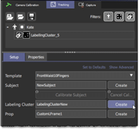
- A labelling cluster will be created from the selected markers. A .vsk file with the same name as the labelling cluster will also be created.
- To Rename, detach, delete, or export a cluster, Right-Click the cluster at the top of the Tracking panel and select the required option. You can also Double-Click a cluster in the tracking panel to rename it.
Check the Selected Marker Count
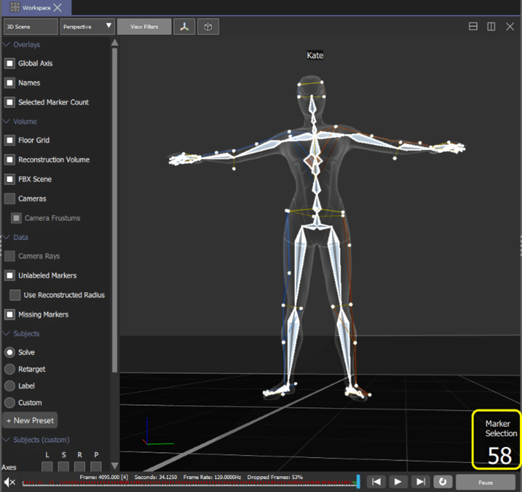
To quickly count the number of markers attached to the performer, you can use the Selected Marker Count in the bottom right corner of the view pane.
- In the 3D Scene view, under View Filters > Overlays, turn on Selected Marker Count.
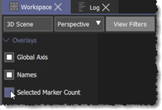
- At the bottom right of the view pane, the Marker Selection count is displayed. If no markers are currently selected, a 0 (zero) is displayed.
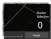
- As you select markers in the view pane, the Marker Selection counter changes to reflect this.
Create Subject
Creating a subject helps the software identify which performer it is tracking in the volume.
To create a subject, the performer stands in an A-Pose at the centre of the volume wearing one of the marker sets described above.
Because the software knows which marker set is being used and how the markers will be arranged when the performer is standing in the A-Pose, it can use this information to identify and label them.
Once the software knows where the markers are, it can use their position to create a skeleton that matches the performer’s proportions.
It can then use all this information to detect the subject (performer), track the marker positions and calculate how the skeleton is moving.
- Set the View Filters at the top of the 3D Scene view.
- Under the Volume options, deselect Cameras.
- In the Subjects section, select Solve and in the “S” column of the Subjects (custom) matrix, select Skin (plus any other options that you want to use).
- In the Data section, select Missing Markers to display occlusion fixing in red. “Occlusion Fixing” uses the position of unoccluded (visible) markers to calculate or “rebuild” the position of occluded (missing) markers. To turn off occlusion fixing, in the Processing tab click Show Advanced > General > Occlusion Fixing.
- In the Tracking panel, under Setup > Template, choose the appropriate marker template for your subject. For example, Production.
- Turn on Show Advanced and select the mesh that will be used for the solving skeleton from the Skins list. For example, ViconMale_v2 or ViconFemale_v2.
- Using a character skin will make it much easier to visualise how well the systems is identifying and tracking the markers, especially on the hands which can often be wrongly identified and solved upside down.
- OPTIONAL – Deselect Calibrate on create. This will allow you to create all the subjects you need for the session while the performers are still getting ready. It also gives you more time to position your performer in the A-Pose.
- To assign a labelling cluster to the subject, turn on Advanced properties, and in the Labelling Cluster Selection field, select one of the following options:
- All = Any currently unattached labelling cluster will be assigned to the subject.
- Selected Only = the cluster(s) selected at the start of calibration will be assigned to the subject.
- None = No labelling clusters will be used for calibration.
- Enter the name of your performer in the Subject field.
- Click Create.
Stand In A-Pose
Ask your performer to stand at the centre of the volume facing down +Y, in the A-Pose:


- Feet should be about hip width apart, underneath the hips.
- The tip of the toes should be level and form a line (ideally use a line on the floor).
- Performer should be standing up straight, with their hips over the middle of the feet (this is usually how people stand when relaxed, but check your performer is not leaning too far backwards or forwards).
- Waist, chest, neck, and head should be relaxed, and straight.
- Feet, waist, chest, and head should all be pointing forwards.
- Performer must be looking directly ahead. The system cannot tell which way the head is facing so assumes it is pointing forwards. Check your performer is not looking to one side listening to instructions or looking at a screen.
- Arms and hands must be straight, rotated away from the body at a 45° angel, palms down, in line with the torso.
- Fingers must be straight.
- If you’re using a template that includes fingers, make sure:
- The wrists are straight.The fingers are straight, with a natural spread, but no bend.The thumb is held tight against the index finger.
- The thumb and fingers all point in the same direction.
Calibrate Subject
- Once the performer is in the correct A-Pose, click Calibrate Subject (this assumes Calibrate on create is turned OFF)
- On the menu bar above the workspace, Subject Calibration Active and a flashing red circle will be displayed.
- If the system has recognised the A-Pose, the markers will be labelled and the labelling and solving skeleton will be displayed in the 3D view.
- Calibration feedback showing the number of markers found and the number of markers required, will be displayed in top right corner of view pane.
- Visually check all the markers have been labelled correctly and the pose of the character in the software matches to pose of your performer in the volume. Pay close attention to the hands and check they are the right way up.
- When you are happy with the A-Pose, click Accept A-Pose on the Setup tab.
- As soon as you Accept A-Pose, you can begin the Range of Motion (ROM).
Perform a Range of Motion
When you accept the A-Pose, the software automatically creates a generic “solving” skeleton based on the position of the markers. To improve the joint positions and increase the accuracy of the data, your subject must perform a Range Of Motion (ROM).
The software uses the ROM to refine the position of the solving skeleton’s joint centres to match the performers. It also uses the motion to learn how the markers move in relation to each other to help improve the estimations of where a marker should be if it cannot be seen when occluded.
To improve the accuracy of the solving skeleton, your performer needs to move every joint through its entire range of motion.
| TIP Ask your performer to keep their arms in a T-Pose while performing the ROM. This will help reduce marker occlusion and improve balance, especially during squats and lunges. |
Suggested Range of Motion:
Head
- Look Left and Right
- Look Up and Down
- Tilt head Left and Right
- Thrust head forward and Back
Arms
- Raise arms over head, palms down (flap)
- Lower to T-Pose
- Turn palms up, raise arm overhead (Clap)
- Lower to T-Pose
- Rotate wrists
- Rotate elbows
- Rotate shoulders
- Reach as far in front as possible – include shoulders
- Reach as far behind as possible
- Return to T
Torso
- Twist Left and Right
- Raise arms above head and bend to left and right
- Return to T
- Bend forward at waist and touch toes
- Lean as far back as possible
- Rotate hips clockwise
- Rotate hips counter clockwise
Legs
- Lift right leg to front, bend at knee and circle out to side and back to floor.
- Lift left leg to front, bend at knee and circle out to side and back to floor.
- Kick right leg forwards, backwards, out and across
- Kick left leg forwards, backwards, out and across
- Lift right heel and rotate at ankle with toes on floor
- Lift left heel and rotate at ankle with toes on floor
- Deep (Asian) squat
- Lunge right leg forward
- Lunge left leg forward
Fingers
- Bend fingertips
- Make a Fist
- Wiggle the fingers
- Touch the tip of the thumb against the tip of each finger of the same hand:
- Thumb to index finger
- Thumb to middle finger
- Thumb to ring finger
- Thumb to pinkie
- Spread open and closed
When the ROM is complete, click Stop Calibrating. The ROM is recorded in the Capture Data tab as <subjectName>_YYMMDDHHMMSS
You are now ready to calibrate the next subject or capture your first take.
| IMPORTANT If your performer needs to remove or adjust the suit for any reason once they have been calibrated, for example to use the bathroom, always try to recalibrate them as soon as possible before capturing any more data. |
Capture a Take
Vicon Shogun Live records the real-time data for every take you capture directly to disk as an .mcp or “mocap” file.
Each .mcp file contains the following information:
- a copy of the current calibration,
- active subject(s),
- real-time capture data,
- paths to the .x2d (an XML file containing 2D camera data),
- paths to any video cameras in the system.
You can replay and review a captured take in the software as soon as you stop or “cut” the capture.
Set Capture Options
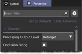
- In the Processing > General tab, set the Processing Output Level to Retargeting (default) or Solve and turn Occlusion Fixing ON. If the system is set to Reconstruct or Label, it will only save reconstructed data. This means you will not see a solving skeleton when you open the data in Post.
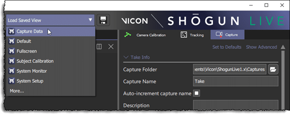
- Switch to the “Capture” tab in the top right of the window. You can also change the view layout to Capture Data from the Load Saved View list at the top right of the menu bar.
- In the Take Info section, click the folder icon to the right of the Capture Folder field. Browse to the directory you want to save you captured takes. Alternatively, you can use Vicon Eclipse to create the directory structure for your session.
- Open Vicon Eclipse.
- Click Create a new database.
- In the New Database dialog box:
- In the Location field, browse to the folder the captured data will be saved.
- In the Name field, enter the name of the project.
- In the Based on list, click “Shogun Animation Template.eni”.
- Click Create. This will create a folder in the “Location” directory using the name you entered in “Name” field.
- In the Open Database dialog box, select the database (project Name) you just created and click Open.
- In the Data Management pane:
- Right-click in the window and select New > Project. Enter the name of the project.
- Select the Project line you just created, then right-click and select New > Capture day. yyyy_mm_dd
- For a full day shoot, Right-Click in the new Capture day, and select New > Session. AM or PM.
- Eclipse will set the Capture Folder using the directory structure you have just created.
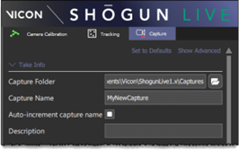
- Turn Auto-increment capture name ON to add and update the take number at the end of the Capture Name.
Capture
- Enter the name of the take in the Capture Name text box.
- When you are ready to record a take, click Start Capture in the Data Capture panel (bottom right corner). The mocap data is recorded to disk at the source frame rate (fps). Capture Active and a flashing red circle are displayed at the top of the window.
- Click Stop Capture to “Cut” and end the capture.
- The captured data is saved to the Capture Folder path using the “Capture Name” from the Take Info section.
| TIP Where possible, ask the performer(s) to start and/or end each take standing spread out in a T-Pose. – If the performers are starting in a T-Pose, start the capture “rolling” and then ask the performer(s) to get into “first” or “start” positions. Then call “Action”. – If the performers are ending in a T-Pose, wait for the director to call “cut” and then ask the performers to spread out and stand in a T-pose BEFORE you stop the capture (cut). – Or do both if you’re unsure. The T-Pose is important if a lot of markers are going to get covered or hidden (occluded) from the cameras or if the performers are going to be performing complex interactions. The T-Pose will provide a few frames in the data where all the markers are visible to the cameras and software. This will help with labelling and tracking during the live capture and in post when someone will have to “track/clean” the data. |
Review
Shogun Live lets you to replay a take as soon as you’ve captured it. Mocap (MCP) review enables you to review a take (.mcp file), update any notes about the take, or investigate technical issues, all without leaving the live software.
When you’ve finished reviewing the take, you can immediately resume capturing.
- Check you have at least one take in the Session folder (see Capture a take).
- In the Capture tab, click the required take in the Review list.
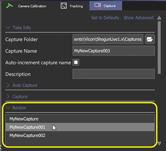
- You can change or update the Description and Notes fields at the bottom of the Review section.
- To review a take, double-click the take name in the Review list. The viewer will change from the live view of the performer(s) in the volume, to the captured data in the take.
- “Review” followed by the name of the selected take will appear in the centre of the menu bar at the top of the Shogun Live window.
- At the bottom of the screen, the time bar displays the current frame, timecode, and duration.
- To review the file:
- Click the Play/Stop button to play the take.
- Skip to the start or end of the take using the “Go to beginning” and “Go to end” buttons to the right of the time bar
- Step through the take frame-by-frame using the default “A” and “S” hot keys.
- To close review mode and return to capturing, click the exit button (X) to the right of the “Review <take name>” in the menu bar.

| NOTE Shogun Live is either in capture mode (live) or in review (playback) mode. You cannot view both live and captured data at the same time or compare two captured takes. |


Leave a Reply